Stereo photogrammetry#
Two views of the same patch of ground from different angles produce parallax: a pixel shift between images that encodes ground height.
What ASP actually computes#
For every pixel in the left image, parallel_stereo searches the right image for the best-matching pixel. The result is a disparity map: a per-pixel shift between the two images. ASP computes it in stages, writing each to disk: an initial whole-pixel disparity (run-D.tif), a subpixel refinement (run-RD.tif), and a filtered final version (run-F.tif). Triangulation then combines each matched pair with the camera models: the two viewing rays are intersected in space, and the intersection is a 3D ground point.
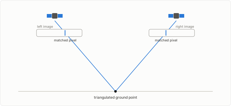
The triangulated points land in a point cloud (run-PC.tif), which point2dem grids into a DEM. See Pipeline overview for where this sits in the full flow.
Camera models#
Triangulation works because each camera model can turn a pixel into a viewing ray. A camera model is the mapping between image pixels and ground coordinates; it encodes where the satellite was, how it was oriented, and how its optics project the scene onto the detector. Orbital imagers are push-broom sensors that acquire one image row at a time as the satellite moves, so position and orientation are functions of time across the image.
Vendors describe that geometry in two main forms. RPC replaces the vendor’s rigorous physical model with fitted ratios of polynomials that map longitude, latitude, and height to the matching pixel. The coefficients are compact, sensor-agnostic, and fast to evaluate, and they keep the physical details (orbit, pointing, optics) private; the cost is a black box that can only answer where a ground point lands in the image. Most commercial Earth imagery ships with RPC. The WorldView XMLs in this guide carry both an exact linescan model and an RPC fit; ASP detects the exact one and uses it by default.
The Community Sensor Model (CSM) is the other direction: a community standard interface for rigorous models, not an approximation. ASP ships the open USGS implementation (usgscsm), whose state files spell out the sensor’s trajectory, orientation over time, and optics. Because those physical parameters are exposed, ASP can adjust them; that is what makes jitter correction possible, and jitter_solve works only with CSM cameras.
Knobs that matter#
The matcher (--stereo-algorithm) and the subpixel refiner (--subpixel-mode) are the two parameters that most affect quality and runtime. The same 800 m crop of the WorldView tutorial pair, run four ways (asp_bm does not support subpixel mode 9, so its quality mode here is 2):
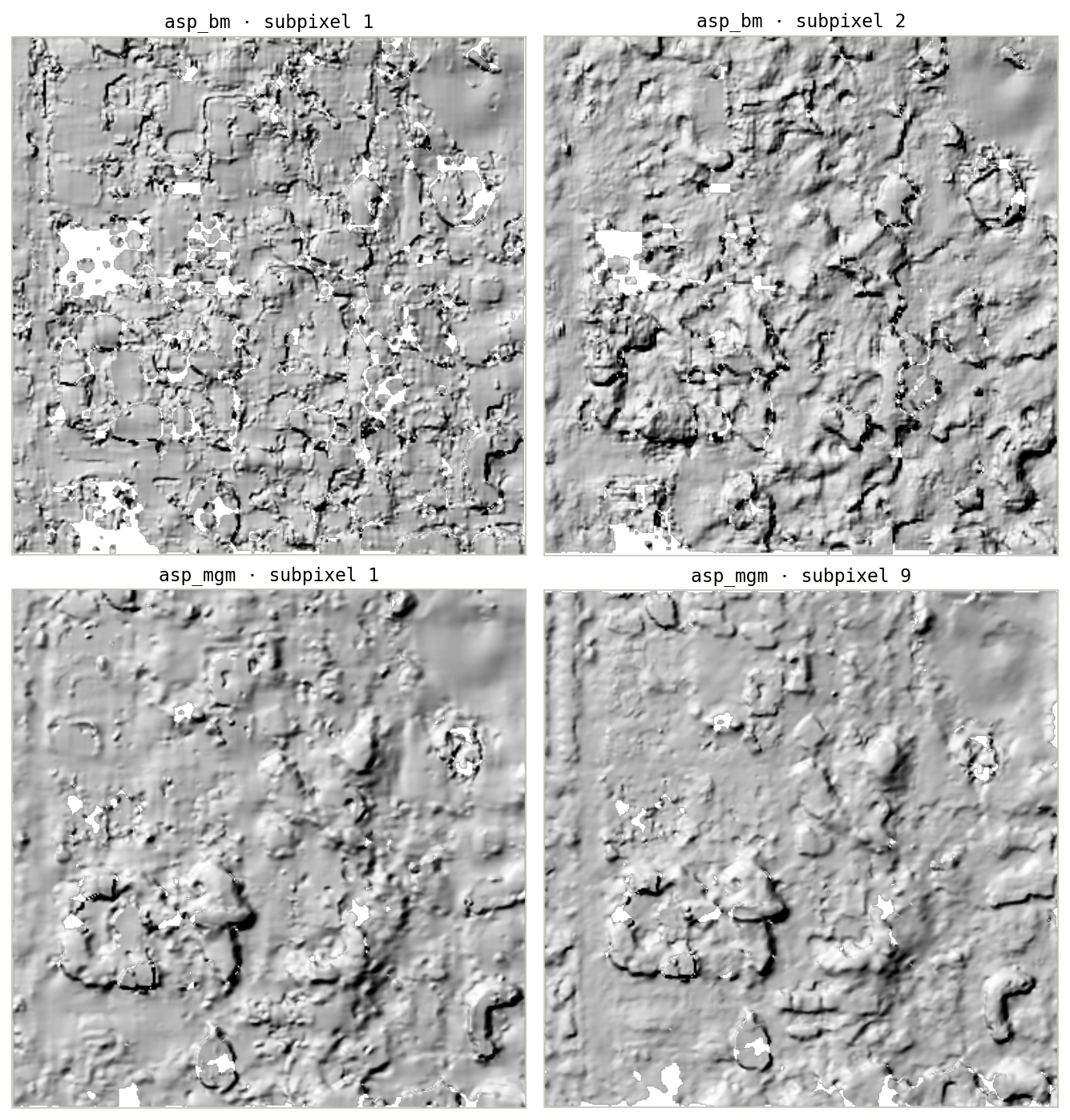
asp_bm is ASP’s classic block matcher, fast and effective on well-textured images; asp_mgm costs more compute and memory and does better where texture is poor or repetitive. The tutorials pair asp_bm with --subpixel-mode 1 for the quick first ASTER pass and asp_mgm with --subpixel-mode 9 everywhere else; the ASP correlation docs describe the full menu.
Geometry that matters#
Height precision is set before you run anything, by the viewing geometry: the convergence angle (the angle between the two viewing rays) and the base-to-height ratio. Too little convergence and the rays intersect at a shallow angle, so small matching errors become large height errors; too much and the two images look so different that matching degrades.
Both quantities come from the vendor metadata. asp_plot.stereo_geometry.StereoGeometryPlotter reads the camera XMLs and plots them, as run in the WorldView tutorial for its stereo pair:

The skyplot (left) shows where each satellite sat in the sky when it imaged the ground; the map (right) shows the ground tracks and the shared footprint. The header lists the derived quantities, including the convergence angle and base-to-height ratio.
Where matching fails#
Featureless surfaces (open water, fresh snow, sand), repetitive texture, occlusion (one camera sees a slope face the other cannot), clouds, and illumination differences between acquisitions all break the matcher. Failures show up as red in run-GoodPixelMap.tif (successful matches are gray) and as voids in the DEM. The maps below are from the two tutorials’ raw first runs:
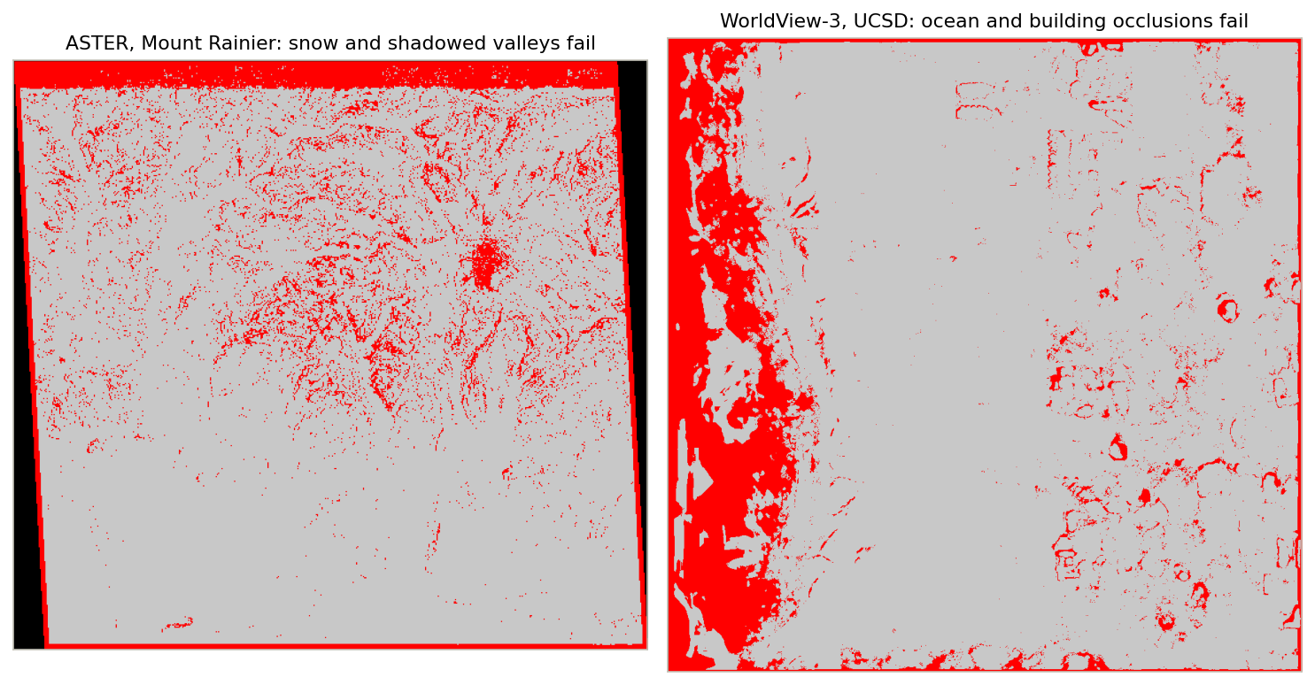
Voids in reasonable places are normal; voids everywhere usually mean a geometry or preprocessing problem, not a matching problem.