Bundle adjustment#
The vendor’s camera models are slightly inaccurate; bundle adjustment refines them by minimizing reprojection errors of features matched between the input images.
What the optimizer does#
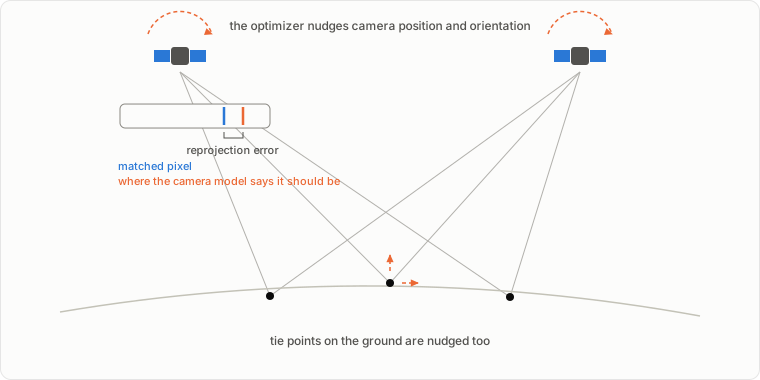
bundle_adjust detects interest points in each image, matches them across images into tie points, and then jointly varies the camera parameters and the tie point positions to shrink the reprojection errors: the distance between where each tie point actually appears in an image and where the camera model says it should appear.
Why this matters for stereo#
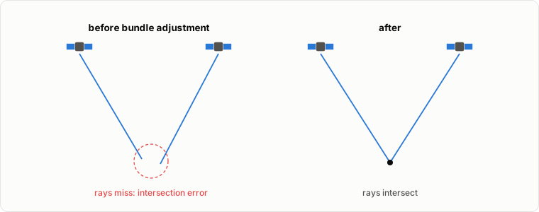
With misaligned cameras, the two viewing rays for a matched pixel do not quite meet. Triangulation records that miss distance per point as the fourth band of run-PC.tif (point2dem --errorimage grids it into run-IntersectionErr.tif), and the misalignment surfaces in the DEM as bias and tilt. Bundle adjustment shrinks all of these.
What it looks like on real data#
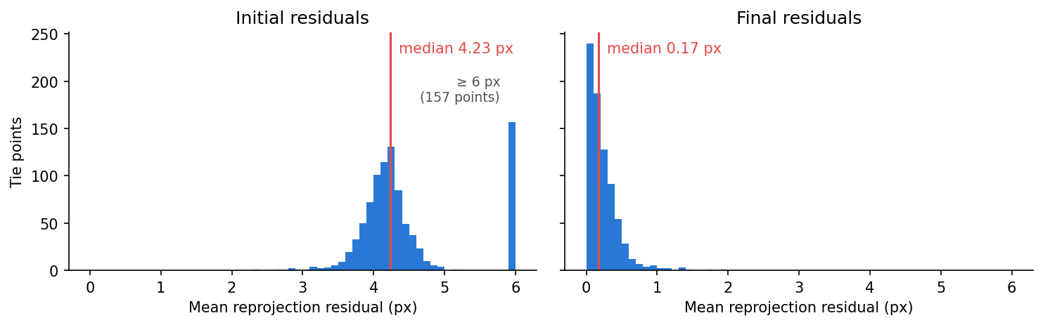
From a bundle_adjust run on the WorldView tutorial’s stereo pair, the per-tie-point reprojection residuals before and after optimization:
The same residuals in map view over the scene footprint (initial values above 10 px are shown clipped):
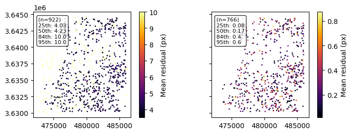
Both figures come from the residual point maps bundle_adjust writes (*-initial_residuals_pointmap.csv, *-final_residuals_pointmap.csv), read with asp_plot.bundle_adjust.PlotBundleAdjustFiles. Look for two things: the residual hump moving toward zero, and no strong spatial pattern left in the final map.
What bundle adjustment cannot fix: jitter#
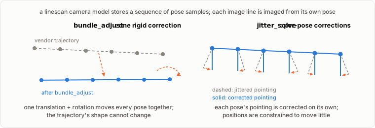
A linescan camera model already contains the sensor’s full trajectory: a time-sampled sequence of positions and orientations, with each image line imaged from its own interpolated pose. bundle_adjust does not touch those samples individually. It solves for one translation and one rotation per camera and applies them to the whole trajectory as a rigid body. That corrects the bulk error in absolute position and pointing, but it has no degrees of freedom to change the trajectory’s internal shape.
Jitter is the high-frequency error left behind. Vibrations during the scan make the pointing oscillate faster than the sampled trajectory captures, and those oscillations imprint a wavy pattern into the image and the DEM. ASP treats it as a separate problem: jitter_solve optimizes the pose samples individually, so it can bend the trajectory to remove the line-to-line perturbation.
|
|
|
|---|---|---|
Free parameters per camera |
one position + one orientation |
a sequence of positions and orientations |
Error corrected |
bulk, low-frequency position and pointing |
high-frequency along-track oscillation |
Output |
|
full CSM camera state |
Typical order |
first |
after bundle adjustment |
jitter_solve normally starts from bundle adjustment’s output, works only with CSM cameras, and needs constraints (anchor points, camera position uncertainties) to keep its many free parameters stable. The tutorials here do not run it; the asp-plot example notebooks include a jitter correction walkthrough.